Driver wheel (rueda o polea motriz) it is the wheel moved directly by a motor or engine.
Driven wheel (rueda conducida) it is the one to which the motion is transmitted.
The motion to the driven wheel is transmitted by means of friction existing in the contact of both
wheels. Consequently, both wheels rotate in opposite direction.
Notice that always the smallest wheel spins the fastest. In exchange its torque (rotary strength) is the lowest. To calculate the speed of the driven wheel we employ the equation
| D1 · N1 = D2 · N2 |
D1 = diameter of the driver wheel.
D2 = diameter of the driven wheel.
N1 = speed of the driver wheel, usually in revolutions per minute (rpm).
N2 = speed of the driven wheel (rpm)

Transmission Ratio
The speed ratio between the driver and driven wheel is calculated as follows:
| µ = N2 / N1 |
Relation with the SPEED
µ > 1 Increase | µ = 1 Equal | µ < 1 Decrease
Belts and Pulleys systems

It is used to transmit motion between two parallel axles.
A belt passes around two pulleys wheels. Then when the driver pulley moves, it moves the belt and the belt moves the driven pulley. Both pulleys wheels rotate in the same direction.
The transmission speed ratio is the same as in the friction wheels. So the equation is exactly the same.

This system is widely used in washing machines, pillars drills, cars etc.
In this type of mechanism slipping may be a problem (or not). To avoid slipping, toothed pulleys and belts are used
Fill the table with the speed rotation of the chuck of a pillar drill whose internal transmission system has two cone pulleys joined by a belt as shown in the picture. Calculate all the possibilities considering the motor which moves the driver pulley rotates at 2300 rpm. (note: all the diameters are in mm)

| Pulleys joined | Driven Speed | |
| 1 gear | 45-115 | |
| 2 gear | 70-90 | |
| 3 gear | 95-65 | |
| 4 gear | 120-40 |

The figure on the left shows the pulley trains with belt of a power drill. Depending on the pulleys combination we select, we can get different speeds in the drill bit. (broca)
a) Which combination of pulleys will allow us to get the slowest speed in the drill bit?
b) Which combination of pulleys will allow us to get the fastest speed in the drill bit?
c) If the engine spins at 1400 rpm, What’s the minimum speed the drill bit can rotate?
Gears – Types of gears
Gears come in a variety of sizes with the teeth straight or curved and inclined at a variety of angles. They are connected together in various ways to transmit motion and force in machines. However, there are only four basic types of gears. They all act so that one gear wheel turns faster or slower than the other, or moves in a different direction. A difference in speed between two gears produces a change in the force transmitted.
RACK AND PINION GEARS
One Wheel, the pinion, meses with a sliding toothed rack, converting rotatory motion to reciprocating motion and vice versa
WORM GEARS
A shaft with a screw thread meshes with a toothed wheel to alter the direction of motion, and change the speed and force.
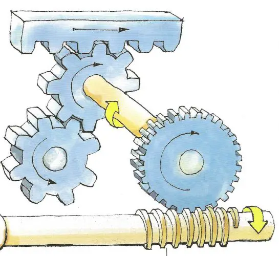
SPUR GEARS
Two gear wheels intermesh in the same plane, regulating the speed or force of motion and reversing its direction
GEARS
The big wheel has twice the number of teeth, and twice the circumference, of the small wheel. It rotates with twice the force and half the speed in the opposite direction.
The way gears and belts control movement depends entirely on the sizes of the two connecting wheels. In any pair of wheels, the larger wheel will rotate more slowly than the smaller wheel, but it will rotate with greater force. The bigger the difference in size between the two wheels, the bigger will be the difference in speed and force. Wheels connected by belts or chains work in just the same way as gears, the only difference being in the direction that the wheels rotate.


To calculate the speed of the driven wheel we employ the equation
| Z1 · N1 = Z2 · N2 |
Z1 = number of teeth of the driver wheel.
Z2 =number of teeth of the driven wheel.
N1 = speed of the driver wheel, usually in revolutions per minute (rpm).
N2 = speed of the driven wheel (rpm)
Transmission Ratio
The speed ratio between the driver and driven wheel is calculated as follows:
| µ = N2 / N1 |
Relation with the SPEED
µ > 1 Increase | µ = 1 Equal | µ < 1 Decrease
 We have a gear system formed by two gears with 20 and 40 gears teeth (driven and driver gear respectively).
- Calculate how fast is spinning the driven gear if the driver gear rotates at 3000 r.p.m.
- Calculate the Transmission Ratio.
Transformation of movement mechanisms
FROM ROTARY TO LINEAR
RACK AND PINION SYSTEM
This uses a pinion that is a small cogwheel, mounted on a rack that is a toothed belt or bar.

A rack and pinion is commonly found in the steering mechanism of cars.
NUT AND BOLT SYSTEM
This consists of a bolt or threaded bar and a nut that has the same interior diameter as the diameter of the bolt.
If the bolt rotates and the nut can’t turn, the nut moves in a linear motion along the threaded axle. If the nut rotates at a fixed position, the bolt will move in a linear motion

WINCH AND CRANK HANDLE
This is a drum that rotates and a crank handle that allows us to lift objects.
The effort needed to turn the winch is less than it would be if we tried to turn it without the crank handle.
A winch is balanced when satisfies this equation:
F x d = R x r
F = Force needed to pull the load or resistence.
d = distance of the handle to the center.
r = radius of the crank.
R = Load or Resistence.

FROM ROTARY INTO RECIPROCATING
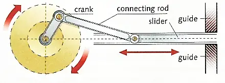
CRANK-LINK-SLIDER
This is composed of a crank and a rod called connecting rod or link.
This rod has articulated joints at each end – one is connected to the crank and the other to the slider.
The slider produces a reciprocating motion.
CAM
This is a basically a rotating object that pushes a follower
as it moves.
A cam transforms rotary motion into reciprocating motion
in the follower or bar.


ECCENTRIC CAM
This consists of a wheel with an off-centre rotation axle that doesn’t coincide with the centre of its circumference.
It transforms the rotary motion of the wheel into reciprocating motion in the connecting rod.
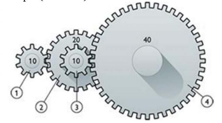
COMPOUND GEAR
A compound gear is a number of gears fixed together. Consequently, they rotate at the same speed.


GEAR TRAIN
A series of gears and compound gears connected.
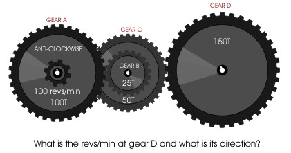
This is an example of a “compound gear train”. Gear A rotates in an anti-clockwise direction at 100 r.pm. What is the output in r.p.m. at D and what is the direction of rotation?
Calculate the “Transmission Ratio” for each pair of gears and the Total Transmission Ratio.
Calculate the gear ratio of the system and the speed of each gear if the driving gear (4) rotates at 800 rpm.(clockwise)